Your cart is currently empty!
Tag: System Configuration

Parallel VS Series: the solar panel edition
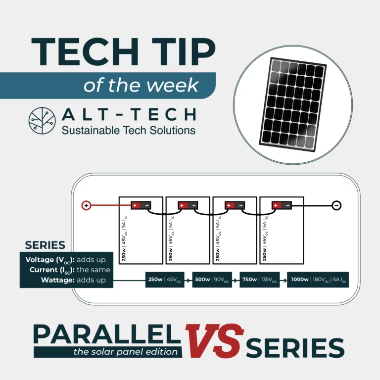
When panels are in series the voltage adds up and the current remains the same, whilst in parallel the voltage remains the same and the current adds up, the wattage will always increase in both configurations.
For example:
Four 250W panels with the specifications of 45Voc and 5A (Isc) in series will total to 1000W, 180Voc and 5A (Isc).
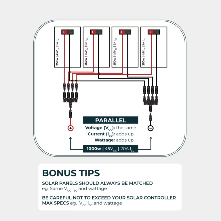
Four 250W panels with the specifications of 45Voc and 5A (Isc) in parallel will result in 1000W, 40Voc and 20A (Isc).
A couple of useful bonus tips:
- Panels should always be matched, e.g. the same Voc, Isc and wattage.
- Check the specs of your solar controller and be careful not to exceed the max Voc, Isc and wattage.

Parallel VS Series: the battery edition

When configuring a smart shunt or battery monitor, a common mistake we see is people adding up both the amp-hours and the voltage of their battery bank, ending up with a much higher figure for amp-hours than they really have.
Remember:
When batteries are in series, voltage increases whilst amp-hours remains the same.
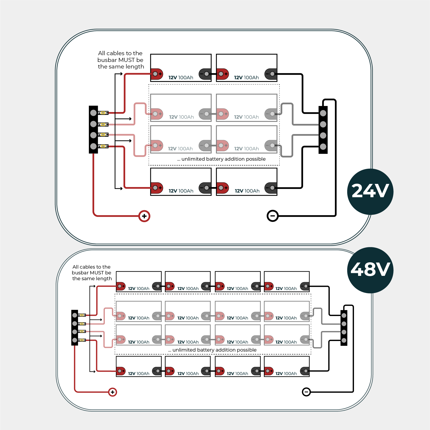
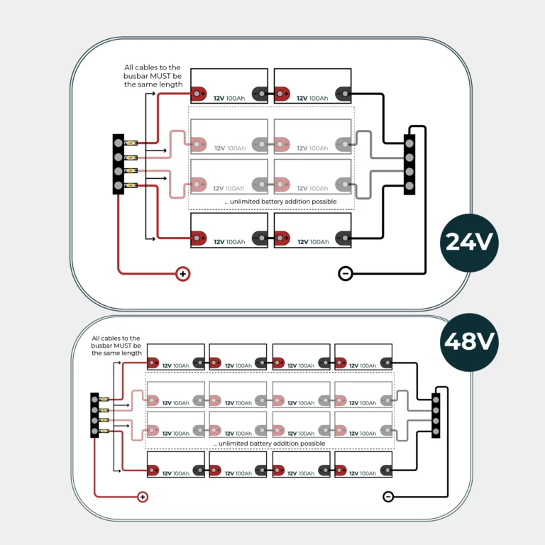
For example:Four 12v 100Ah batteries in series will result in 48v, 100Ah with 4800wh capacity. When batteries are in parallel amp-hours increase but not voltage.For example: Four 12v 100Ah batteries in parallel will result in 12v, 400Ah giving 4800wh capacity.These battery wiring diagrams help illustrate the difference in parallel and series configurations.
Please be aware: parallel banks require fusing when combining with a distribution system as illustrated in the 24V & 48V diagram.

Tilt Angle & Performance
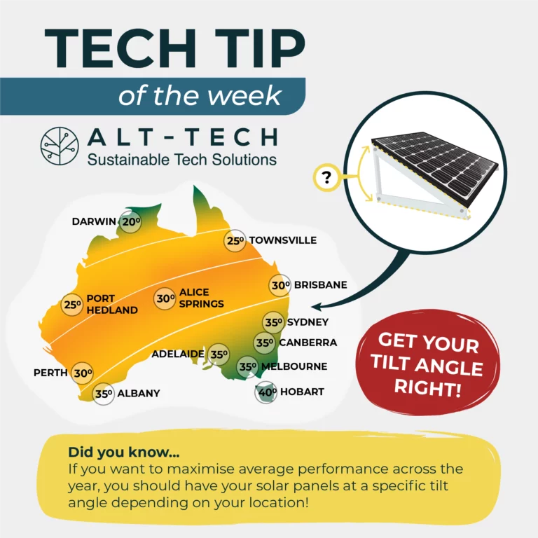
If you want to maximise average performance across the year, you should have your solar panels at a specific tilt angle depending on your location.
- In Perth the best angle is 30º, the same as in Brisbane and Alice Springs.
- Further North in Port Hedland you’re looking at 25º, the same as Townsville.
- Down South in Albany, 35º is ideal, an angle shared by Adelaide, Canberra, Melbourne and Sydney.
- At either end of the tilt angle spectrum in Australia sit Darwin at 20º and Hobart at 40º.
We sell a variety of tilt frame options to help you optimise your panel performance. If you are someone who has more than enough performance in summer but are looking to boost winter performance, you can even add 5 degrees to your tilt.

Fuses: Safeguarding your System Wiring
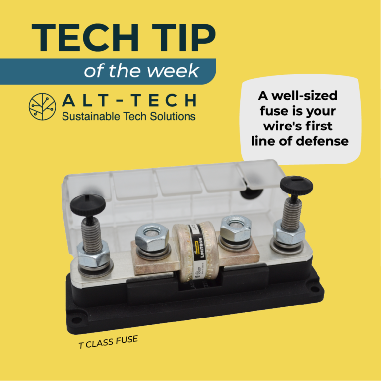
When calculating the fuse for your system, remember: The fuse’s primary role is to safeguard the wire’s integrity.
They shield against potential fire hazards by breaking the circuit if something goes wrong.
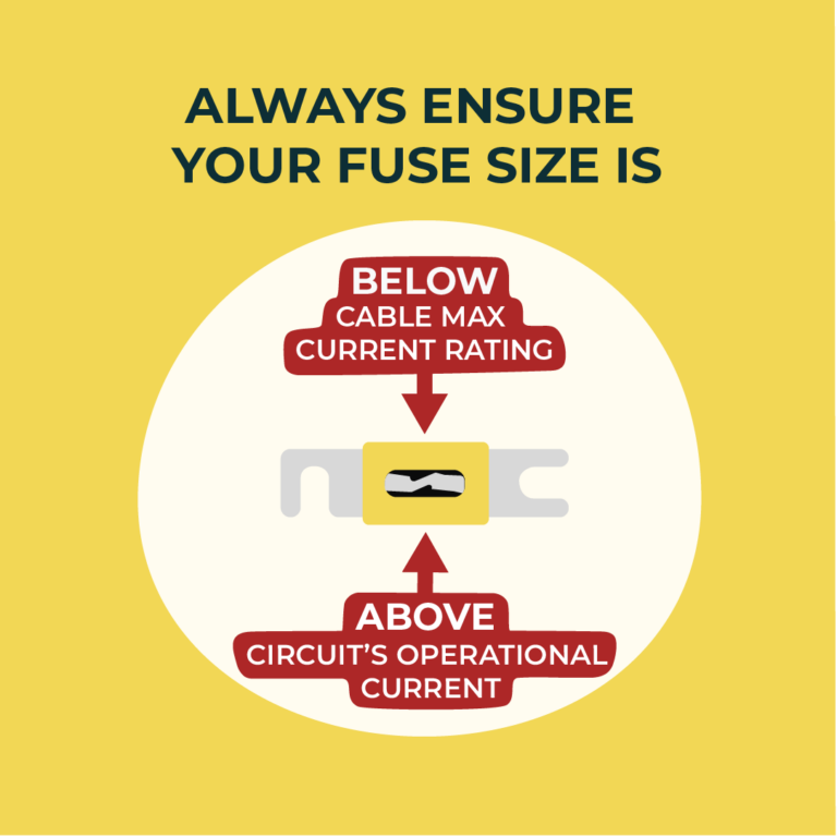
- Ensure your fuse size is above the circuit’s operational current and below the wire’s maximum current rating.
- Prioritize system safety by understanding that a well-sized fuse is your wire’s first line of defense.
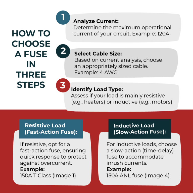
The following three steps will help you determine the best type and size of fuse for your system.
- Analyze Current: Determine the maximum operational current of your circuit. Example: 120A
- Select Cable Size: Based on current analysis, choose an appropriately sized cable. Example: 4 AWG.
- Identify Load Type: Assess if your load is mainly resistive (e.g., heaters) or inductive (e.g., motors).
Resistive Load (Fast-Action Fuse):If resistive, opt for a fast-action fuse, ensuring quick response to protect against overcurrent. Example: 150A fast-blow fuse.
Inductive Load (Slow-Action Fuse):For inductive loads, choose a slow-action (time-delay) fuse to accommodate inrush currents. Example: 150A time-delay fuse.
Check Manufacturer Recommendations when possible! If you need more advice our sales team are always happy to help.
Shop Fusing
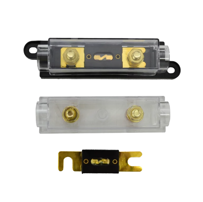
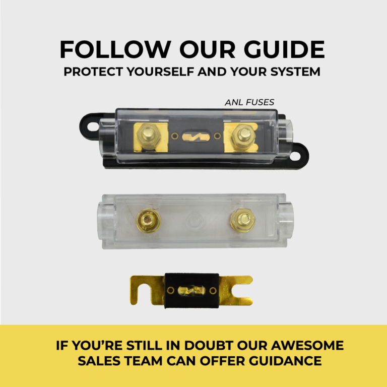
Fusing
All your off-grid, DC electrical circuit protection needs are covered with ANL fuses, Blade fuses, FH type fuses and Victron megafuses, plus housing and holders.

System configurations – How does all this stuff go together?
System configurations – How does all this stuff go together?
Let’s start with the most basic – a 12 or 24V system used to power DC loads such as a 12/24V fridge, lighting, compressors etc. As a case study (and because it’s around 90% of people who walk through the door) let’s say this is going on a vehicle.
You will need either:
- A solar panel, solar controller, and battery (or several) or
- A DC-DC charger and battery or
- Both.
For a small solar array, panel plugs into solar controller, battery plugs into solar controller. Make sure you put the cables in the correct port and make good connections, and away you go. The controller regulates the voltage going to your battery to avoid overcharging.
There are two main classes of solar controller -MPPT and PWM (There’s a whole other post about the difference between these) – but the takeaway is that an MPPT is more efficient, takes better care of your battery, and will take a much wider range of panels. An MPPT controller will work with 12V panels, but it will also work with a higher voltage panel, which will perform better when conditions are poor.
For a DC-DC system, you run your cable from the starter battery to the DC-DC charger, then from the DC-DC to the second battery. In a vehicle without a smart alternator, earthing the DC-DC to the body of the vehicle is an option, if you have a smart alternator you will need to get an isolated DC-DC and run both a positive and a negative (earth) cable. (A setup using a VSR in stead of a DC-DC charger is a possibility for deep cycle batteries if you don’t have a smart alternator, however you will likely never get a 100% state of charge with just a VSR)
In both cases, you want to fuse everything (including loads) that is connected to the battery. Anywhere the positive and negative cable can physically come into contact (and in a vehicle where the entire body of the vehicle is earthed – where the positive can come into contact with metal) there is a potential for a short circuit, which could cause a fire.
What if you want to run 240V appliances (anything you’d plug into the wall at home) – Get a 240V battery inverter (make sure your battery is capable of handling the load). Bear in mind that if it doesn’t have plugs, you will need an electrician to hard wire the AC side.
Surprisingly, this configuration holds true for much larger systems. A larger array of solar panels and a much larger MPPT controller going to a much larger battery bank, and from there, to a battery inverter. These systems are more complex to setup and require more planning, and as permanent installations, there is more red tape, but where grid power isn’t available yet or has yet to be connected, it can work out far cheaper than paying for a connection and running underground cables.
What about PV inverters? The ones used on grid – tie solar systems? Can those be used?
Yes and no.
PV inverters need to ‘see’ the grid in order to startup, meaning it’s impossile to get a pv inverter started without first having a battery inverter as well. On top of that, the two inverters need to be able to communicate. Once you have a battery inverter and a PV inverter that can talk to each other, you can run them in parallel.
Say you have a 5kVA multiplus and a 5kW Fronius inverter. The AC output of the Fronius connects to the AC output of the multiplus. This gives the Fronius it’s ‘grid’ frequency and lets it start up. On a good day, where the fronius is producing 5kW, you will have up to 10kW available during the day.
If you’re not using that, the excess power is still used to charge your batteries – by going ‘backwards’ through the Victron inverter.
This is generally slightly more expensive than going the MPPT route, but in situations where daytime power use is higher (very popular for irrigation, cool rooms and large aircons) that extra inverter power can make a big difference in system performance