Your cart is currently empty!
Tag: Off-Grid

Chargers & Converters: Whats the Difference?
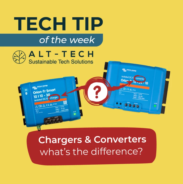
Spot the difference!
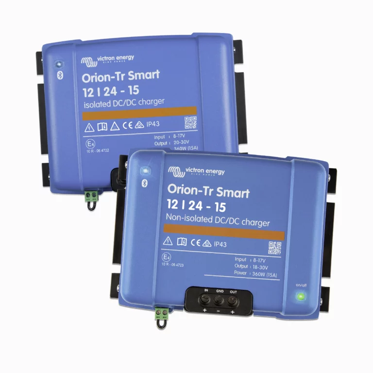
Converters and chargers may look alike and might occupy a similar location in your system configuration but they perform different roles.
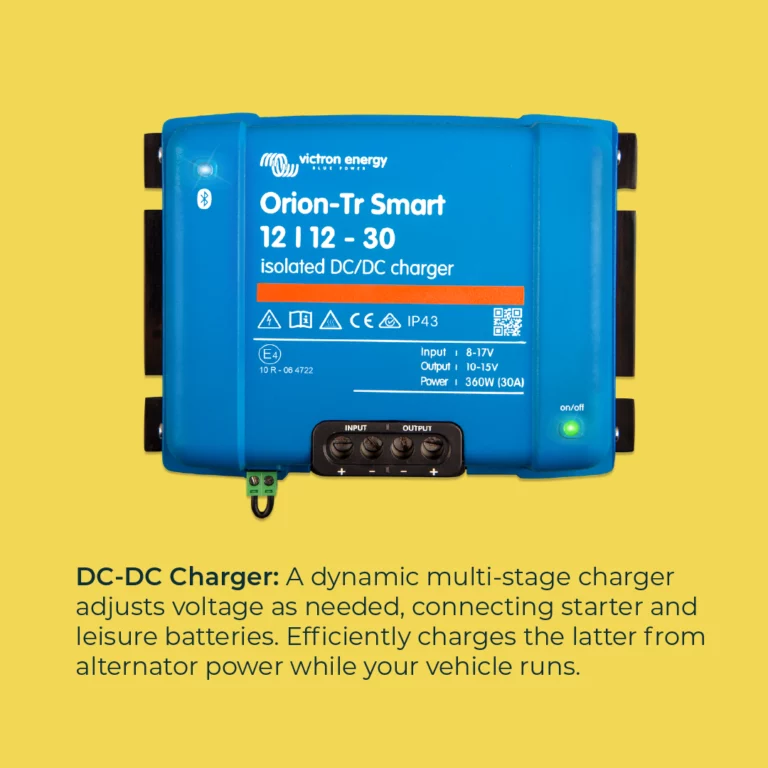
DC-DC Charger: A dynamic multi-stage charger adjusts voltage as needed, connecting starter and leisure batteries. Efficiently charges the latter from alternator power while your vehicle runs.
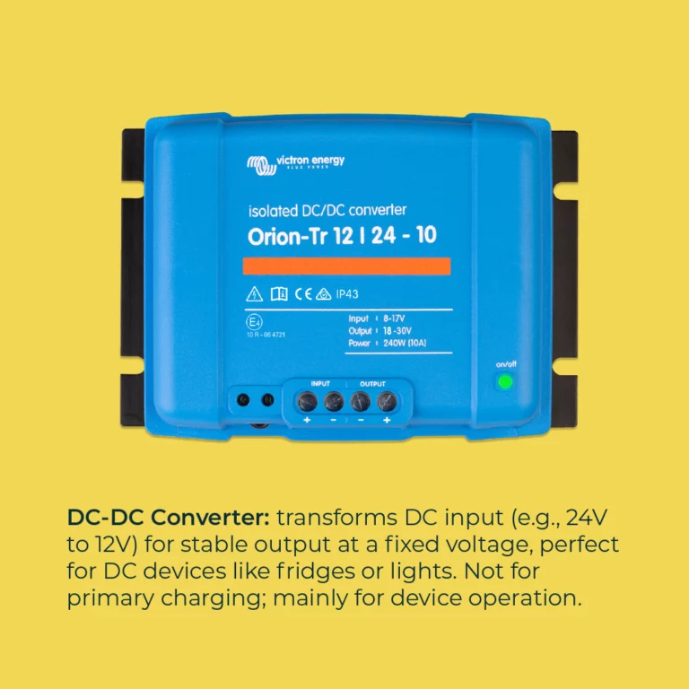
DC-DC Converter: Transforms DC input (e.g., 24V to 12V) for stable output at a fixed voltage, perfect for DC devices like fridges or lights. Not for primary charging; mainly for device operation.
Shop DC-DC Chargers and Converters
DC to DC
Charge and maintain your batteries with DC to DC charging, our range includes convertors and isolated and non-isolated options from brands such as Victron and Enerdrive suitable for 12v, 24v or 48v.

Charge Controllers – What’s the difference?
We’ve talked about the difference between an MPPT controller and a PWM controller, and briefly about sizing your controllers.
MPPT’s use a transformer to step down the Voltage from your solar panel to the Voltage of your battery, usually with an efficiency of over 95%.
The calculation for this is simple. If you have a 200W panel and a 12V battery, divide 200 by 12 to get 16.66 Amps. Conversely, if you have a 24V battery and a 20A controller, multiply 20 x 24 and you get 480W, so that is the size of a solar panel that will give you the full 20 Amps (discounting inefficiency).
Aside from that, you need to make sure the solar panel Voltage is lower than the rated MPPT voltage (i.e. if you controller is only rated for 25V, don’t put a 45V panel on it!)
This is the reason we prefer certain brands of solar controller. House panels tend to be higher quality and higher Voltage, (and lower price), so we prefer an MPPT that will take a house panel.
So this is where it gets more complicated (but I promise – it’s a good thing).
Some MPPT controllers can be ‘overstacked’, meaning you can put some excess power on them. For example, if you have a 12V battery and a 10A controller, that’s 120W of power (or closer to 130 if you account for inefficiency).
Take the Enerdrive, which is a combined DC-DC and MPPT controller with a charge current of 40A at 12V. That should be a maximum of 480W of solar (40 x 12) but on the side of the box it says can take up to 1250W.
Victron MPPT’s are even more complex. Whilst each controller has a ‘nominal’ power on the side of the box (which is already 20% over the controllers rated charge current) if you go into the specs you will find a maximum input voltage and a maximum short circuit input current. Input voltage is based on the open circuit voltage of your panels (not the maximum power) and current is based on the short circuit current. Provided you stay under both of those values, you can often put more than double the power you would otherwise.
What’s the advantage of this?
Panels are cheap (especially secondhand panels. Many of our used panels come out around 30 cents per watt).
Controllers are expensive.
Due to the low cost of panels and relatively high cost of batteries, it’s often desirable to oversize your solar array for those cloudy, rainy days when your solar output is only at 10% – 20% capacity.
By oversizing your array relative to your controller, you are guaranteed the rated output of that controller earlier in the day, and a higher output on cloudy days. Of course there are scenarios where you want the max. output from the panels, such as mobile setups where space is tight, or applications where you use far more power on Sunny days (air conditioning, irrigation etc), but knowing you can overstack a controller can bring down the overall cost of a system without affecting your performance.
A final note on voltage.
That open circuit voltage on the back of the panel is based on the panel being at 25 degrees celsius.
Under colder conditions on a clear day, that Voltage goes up higher than what the panel is rated for.
We had one week last year where three separate people brought in MPPT’s that had died due to overvoltage. All of them were being used with panels that were theoretically 10% under the rated input Voltage. So we recommend staying 20% under the rated Voltage on an MPPT, just to be safe.
Shop Solar Controllers
Regulators
MPPT and PWM charge controllers for regulating amperage and voltage on solar systems including brands such as Victron bluesolar and smartsolar, Epever and Amptron.
Lithium Batteries: Wiring a BMS
A lithium phosphate battery cell is 3.2V nominal (between 2.65 – 3.65V). This is the limit of the cell’s chemistry, so if we want more than 3.2V, we need to put the cells in series. (Translation for people with a social life – connect the positive terminal of one cell to the negative terminal of the next)
2 cells gives you 3.2 + 3.2 = 6.4V, 4 cells gives you 12.8V, 8 cells gives you 25.6V etc.
So if you want a 12V battery (nominal), you put 4 cells in series and charge them up. Simple, right?
That’s how it works with many batteries, but lithium cells tend to become unbalanced. If you put 4 in series and charge the whole pack to 14.2V (3.55V / cell, at which point the battery is fully charged although the cells can technically go a little higher), the charge becomes unevenly distributed. After a few cycles, one cell will reach 3.8V or higher and die.
Enter the BMS, or ‘Battery Management System’. The purpose of a BMS is to balance the cells, and turn off the battery if one cell gets too high or low, so the whole battery doesn’t fail. All BMS systems have cell monitoring and protection, and most have cell balancing incorporated, although some require separate balancing. (note – some BMS’s on the market incorporate a charging system as well. We will be focusing solely on the protection / balancing aspect)
A BMS must monitor the voltage of each cell and be able to shuffle power around in order to keep them at the same level of charge. To do this, a lead is run to each cell. In a 12V system, you will have one wire going to the negative point of the bank, and a wire going to the positive of each cell. The BMS monitors each cell relative to that first negative, so it expects to see 3.2V from the first to the second lead, then 6.4V from the first to the third, etc. For that reason it is very important to get your leads in the correct order (if you don’t your BMS will go pop) – Hint: Use a multimeter to check the voltage at the pins of the plug before you plug in to the BMS.
A BMS must also provide protection. Most BMS boards have the protection incorporated – they will have a copper plate where the output cable can be soldered or bolted to the device itself. One side goes to the battery, the other to your load. If any one cell gets to high or too low, the BMS cuts out to protect the battery bank. Some BMS systems rely on a system of relays in stead, but we will cover the types of BMS more in depth later.
Whilst most BMS systems have cell balancing incorporated, it is generally passive or resistive balancing. It only works in the top 15 – 20% of the charging cycle, and they tend to get hot. With larger cells, or with a battery bank that is working hard, passive balancing may not keep up, causing the BMS to trip more often or the bank to operate at a lower capacity. Active balancing that uses capacitors and operates through the entire charging cycle produces less heat is advisable – by keeping the cells at an even voltage, it ensures each cell gets a full charge with every cycle which improves both the efficiency and the cycle life of the battery.
Further reading
DC Ripple and Batteries
DC Voltage is usually thought of as constant – You have a 12V battery, it outputs a steady Voltage, only changing gradually as it is charged and discharged.
DC ripple occurs when the Voltage of a DC system oscillates, usually only on a scale of milivolts. It can happen for a number of reasons.
- Volt droop – As you discharge a battery, the Voltage drops. Volt droop refers to the phenomenon by which the voltage drops disproportionately low under a heavier load. Say if you discharge a 12V battery from 13V down to 12V. If the load was heavy for the battery’s size and you turn it off once the battery reaches 12V, you will see the voltage come back up – maybe to 12.1, maybe to 12.5 – depending on how heavy the load is. This is not DC ripple on it’s own, but DC ripple occurs due to Voltage droop when loads are uneven – and most loads are. A 240V battery inverter will pull more power at certain points in the wave, which causes the battery Voltage to oscillate at a rate of 50Hz – too quickly to show up on a multimeter, but can be observed on an oscilloscope.
- Charging methods – Most methods of charging a battery do not provide a truly constant voltage to the battery. On the extreme end you have switch mode power supplies and PWM solar controllers which let through high Voltage pulses. Even high quality charging equipment tends to allow small ripples and smart chargers use high Voltage pulses to sense battery Voltage (still go for a 3 – stage charger if you can – the benefits far outweigh the small disadvantage).
- Rapid charge – discharge cycles. So you’re charging your batteries from solar at the same time as you’re using them. Output power isn’t constant, neither is input power, and the load includes an inverter. You have DC ripple due to the inverter power, an uneven draw, and uneven input power all at once.
So why does this matter?
Firstly, at high enough voltages, DC ripple carries similar risks to AC current. This isn’t worth worrying about with a simple 12 or 24 Volt system, but at higher Voltages it is something that professionals need to be aware of. Battery life – DC ripple basically charges and discharges your battery very fast. Whilst only at the scale of mili – or – micro – volts, these mini – cycles do add up and long term shorten the usable life of your battery. How much will depend on the type of battery and the severity of the DC ripple. Batteries with a higher internal resistance experience a greater degree of DC ripple – So lead batteries typically fare worse than lithium batteries of the same size. On the flip side, the high voltage spikes put out by PWM controllers and other cheap chargers are especially damaging to lithium batteries.
What can be done to minimize DC ripple?
- Quality charging – Avoid PWM’s if possible and go for an MPPT, use quality 240V chargers as well if possible.
- Ensure your battery bank is properly sized. Lead batteries shouldn’t be discharged faster than 0.2C, or 20% of the batteries Amp – hour capacity, i.e. if you have a 100Ah battery, you shouldn’t pull more than 20Amps from it. Lithium and lead – Carbon batteries can be discharged faster, so go for these if running heavy loads.
- You knew I was going to talk about supercapacitors. These have a much lower internal resistance than either lead or lithium batteries, and have millions of charge – discharge cycles in stead of mere thousands. With a supercapacitor in parallel with a battery bank, all of those micro – cycles go through the supercapacitor first, buffering or eliminating the DC ripple effect. This is not necessarily a cost effective solution for a small AGM battery, but on larger banks it’s a no–brainer.
System configurations – How does all this stuff go together?
System configurations – How does all this stuff go together?
Let’s start with the most basic – a 12 or 24V system used to power DC loads such as a 12/24V fridge, lighting, compressors etc. As a case study (and because it’s around 90% of people who walk through the door) let’s say this is going on a vehicle.
You will need either:
- A solar panel, solar controller, and battery (or several) or
- A DC-DC charger and battery or
- Both.
For a small solar array, panel plugs into solar controller, battery plugs into solar controller. Make sure you put the cables in the correct port and make good connections, and away you go. The controller regulates the voltage going to your battery to avoid overcharging.
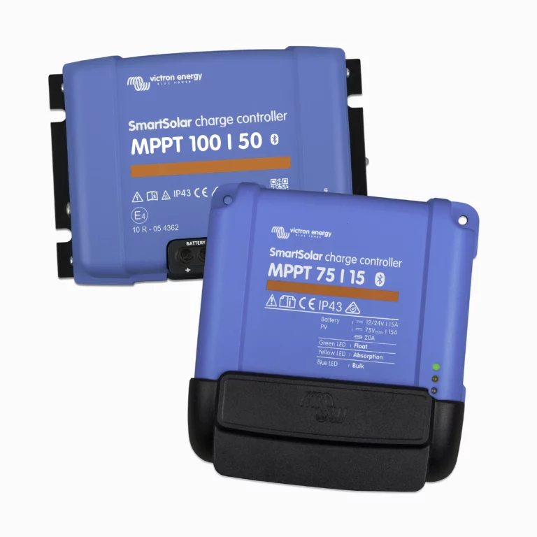
There are two main classes of solar controller -MPPT and PWM (There’s a whole other post about the difference between these) – but the takeaway is that an MPPT is more efficient, takes better care of your battery, and will take a much wider range of panels. An MPPT controller will work with 12V panels, but it will also work with a higher voltage panel, which will perform better when conditions are poor.
For a DC-DC system, you run your cable from the starter battery to the DC-DC charger, then from the DC-DC to the second battery. In a vehicle without a smart alternator, earthing the DC-DC to the body of the vehicle is an option, if you have a smart alternator you will need to get an isolated DC-DC and run both a positive and a negative (earth) cable. (A setup using a VSR in stead of a DC-DC charger is a possibility for deep cycle batteries if you don’t have a smart alternator, however you will likely never get a 100% state of charge with just a VSR)
In both cases, you want to fuse everything (including loads) that is connected to the battery. Anywhere the positive and negative cable can physically come into contact (and in a vehicle where the entire body of the vehicle is earthed – where the positive can come into contact with metal) there is a potential for a short circuit, which could cause a fire.
What if you want to run 240V appliances (anything you’d plug into the wall at home) – Get a 240V battery inverter (make sure your battery is capable of handling the load). Bear in mind that if it doesn’t have plugs, you will need an electrician to hard wire the AC side.
Surprisingly, this configuration holds true for much larger systems. A larger array of solar panels and a much larger MPPT controller going to a much larger battery bank, and from there, to a battery inverter. These systems are more complex to setup and require more planning, and as permanent installations, there is more red tape, but where grid power isn’t available yet or has yet to be connected, it can work out far cheaper than paying for a connection and running underground cables.
What about PV inverters? The ones used on grid – tie solar systems? Can those be used?
Yes and no.
PV inverters need to ‘see’ the grid in order to startup, meaning it’s impossile to get a pv inverter started without first having a battery inverter as well. On top of that, the two inverters need to be able to communicate. Once you have a battery inverter and a PV inverter that can talk to each other, you can run them in parallel.
Say you have a 5kVA multiplus and a 5kW Fronius inverter. The AC output of the Fronius connects to the AC output of the multiplus. This gives the Fronius it’s ‘grid’ frequency and lets it start up. On a good day, where the fronius is producing 5kW, you will have up to 10kW available during the day.
If you’re not using that, the excess power is still used to charge your batteries – by going ‘backwards’ through the Victron inverter.
This is generally slightly more expensive than going the MPPT route, but in situations where daytime power use is higher (very popular for irrigation, cool rooms and large aircons) that extra inverter power can make a big difference in system performance
What if my panels don’t match?
Mismatched panels can be put together in the same string, but there are some rules to follow to keep the system safe and efficient.
In a series string, you need your panels to be the same technology, similar output, and a similar open circuit Voltage. The limiting factor with series panels is the current – if you have a low current, high voltage panel in series with a high Voltage, low current panel, it will limit your output current and potentially overheat the low current panel.
For parallel strings, your panels must be the same technology, your parallel strings must be as close as possible to the same open circuit Voltage (5% out is considered the safe limit), the tilt angle must be within 5%. This is if they are ‘paralleled’ on the roof, without a breaker in between or power conditioning equipment such as micro – inverters.
If you have multiple parallel strings going through breakers, they still need to be the same technology and within 5% Voc, but they may be facing different directions / at different angles.
Are these 12V panels?
In industry, panels that are under 25V open circuit are commonly referred to as ‘12 Volt panels’, which leads people to think that if they have a 12V battery, they need a ‘12 V panel’ (which is actually 24V). Not the case.
There are two basic types of solar controllers – There’s a whole other tech talk on them but it boils down to:
PWM: Can halve the Voltage coming from the solar panel (so can bring 24V down to 12V). Not very efficient, not very good for your batteries in the long run as they tend to let through high frequency Voltage ‘spikes’.
MPPT: Can handle much higher Voltages (Most ‘12V’ MPPT’s take between 45 and 100V max. input). More efficient. Often comes with 3 – stage charging, takes excellent care of your batteries.
This means – With an MPPT, any panel you like can be a 12V panel. Generally speaking, getting a secondhand commercial grade house panel and an MPPT controller is going to cost about the same amount of money as a brand new 12V panel with a PWM (there are good 12V panels and there are also extremely bad ones), and will take better care of your batteries.
What’s the difference between monocrystalline and polycrystalline panels?
Record–breaking efficiency belongs to the monocrystalline panels, but generally speaking a 200W monocrystalline will be the same size as a 200W polycrystalline. Monocrystalline panels generally do better in the heat, polycrystalline panels genrally do a bit better in diffuse light conditions (i.e. partial shade)
What’s the best flexible panel
There are three main types of solar panel cell. Monocrystalline, polycrystalline, and amorphous.
Monocrystalline and polycrystalline are made from silicon wafers. Whilst a few brands like Sunpower have made more flexible cells, all mono-and-polycrystalline cells are brittle. A mono or a poly flexible panel is simply not going to last very long. You’ll get longer if they are framed or if they are mounted well, but you will be lucky to get 5 years from a good one and they often don’t last 2.
Amorphous flexible panels exist. Amorphous solar cells are very flexible and durable, and amorphous flexible panels are very expensive.
What’s the Safest Battery?
The most common batteries used today in small to household – sized setups fall into two categories – Lead acid and Lithium.
Lead
Lead batteries fall into several different categories;
Flooded
Flooded lead batteries are commonly used for cranking (the battery under your bonnet is almost certainly a flooded lead – acid). They contain a liquid Sulfuric Acid electrolyte. Every time the battery is charged or discharged, some of this electrolyte degrades to form hydrogen sulfide gas, which is flammable. Flooded lead batteries can produce enough hydrogen sulfide to build up and explode, so large installations require a specialised ventillation system. Flooded lead batteries can also be spilled; The electrolyte can produce dangerous / flammable fumes depending on what it comes into contact with.
AGM / Gel
AGM and Gel batteries are different but in terms of safety they fall into the same category – Non spillable, valve regulated lead acid.AGM’s immobilise the sulfuric acid electrolyte in a special absorbent glass mat, which reduces the hydrogen sulfide produced. Gel batteries, similarly, contain a sulfuric acid electrolyte that is mixed with a gelling agent. Both of these batteries are recommended to ‘not be charged in a gas tight container’ but are safe to have in an enclosed space such as a vehicle or a building. Lead – Carbon batteries generally are also either AGM or Gel batteries in terms of electrolyte, but because of their better charge / discharge efficiency and their slightly lower operating Voltage, Hydrogen Sulfide production is even lower.
Lithiuim
There are two broad categories of lithium batteries. Lithium – Ion is the general term used for lithium – Cobalt, lithium – manganese and a few other varieties. LFP, LiFePO4, lithium – Iron (not ion), or LiFePO is the term used for Lithium Ferrous Phosphate batteries.
Lithium ion batteries have advantages in weight and charge / discharge ratings but if mismanaged present a serious fire hazard as they contain a flammable electrolyte that bacomes explosive on contact with water.
LFP batteries are comparitively very safe. They handle the heat better and last longer, but are slightly heavier. Whilst the electrolyte is technically still flammable under extreme conditions, fires starting from LFP batteries are exceedingly rare and typically only occur when a high voltage bank gets short circuited, or when battery cells are mechanically damaged and then get wet. Prismatic LFP cells are some of the safest batteries available.
Fusing
Regardless of chemistry, batteries store a lot of energy and an electrical fault caused by a short circuit or an undersized conductor can start a fire simply because of the heat produced by the current. It is essential to ensure that all cables and links are correctly sized. Anything directly connected to a battery should be fused. Single – pole fuses and isolators, by convention, go on the positive terminal of your battery, and with good reason – In a vehicle, the starter battery is earthed to the chassis, i.e. the entire body of the car is negative. This means that if your positive cable comes into contact with the body of the vehicle at any point, it can create a short circuit (in layperson’s terms, this will cause electrical current to be drawn from the battery extremely fast, producing heat, which could case a fire). Fusing any cable going to the positive terminal of a battery, as close to that terminal as possible, is therefore an essential safety measure.
In higher Voltage / stationary systems, a ‘double – pole’ fuse or magnetic circuit breaker is used and generally double – sheath cable or conduit is used between the battery and the breaker. There are strict standards on the protection equipment that can be used and installation layout for larger systems.
Edit: Since this Tech Talk was written we have now added Lead-Carbon to our range. You can read about this technology here:
Victron Cerbo GX
Welcome to anther Tech Talk – where we will be talking about a featured product we are particularly excited about.
Featured product – The Victron Cerbo GX
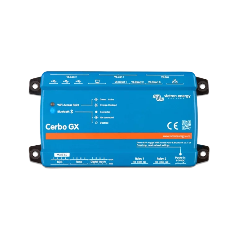
Like all GX devices, this little blue box serves as the brains of your system. The reason we’ve fallen in love with this little guy? – The possibilities are endless. The Cerbo GX has inbuilt wifi and bluetooth, giving you full system monitoring on your phone via the Victron Connect app or on your computer halfway around the world, without running extra ethernet cables.
The Cerbo features the following interfaces:
- 4 digital inputs, which can be linked to anything from burglar alarms to smoke detectors.
- 4 temperature inputs.
- 4 resistive tank level inputs.
- 3 USB ports – GPS, keyboard, wifi dongles, memory and more!
- 2* VE Bus RJ-45 ports
- 4* VE CAN ports
- 3* VE Direct ports
- Ethernet port
- HDMI port
- 2 programmable relays
Aside from giving you full monitoring and control of your energy system, with interfaces for your inverters, solar controllers, battery chargers, battery monitors, smart shunts, energy meters and more
You can also program your system based on a whole range of other factors. You can shut down your energy system when a smoke alarm goes off. You can program it to maintain temperature or water levels, or to prioritize certain functions based on available energy.
Plug in a screen and a keyboard and you have your whole system on a computer.
See the full manual here: Cerbo GX Manual
Shop Cerbo GX

Solar panel wiring
When you have two or more panels, there are a number of ways to wire them up.
We are often asked – ‘What’s better? Putting our panels in series, or in parallel?’
(tl;dr at the end)
Series
Putting panels in series is just like putting battery cells in series – You plug the positive terminal of one panel into the negative terminal of the other. This adds the voltages together (so two 50V panels in series will give you 100V), and the Current from the two panels stays the same. Remember – Power is current multiplied by Voltage, so whether you put them in series or parallel, you are still getting the total power of Panel A + Panel B. There is a common misconception that more amps = more power, but this is not the case if it comes with a reduced Voltage.
Pros: In order for your solar controller to start charging, the Voltage from the panels must be higher than the Voltage of the battery system (In the Victron MPPT’s, at least 5V higher, but it varies from unit to unit). This shouldn’t be a problem with a 50V panel and a 12V battery, but on a cloudy day, early in the morning, and late in the evening, a higher Voltage is going to put more juice into your batteries, even if the total power of the panels is the same. (i.e. 400W of solar at 100V will give you more charge than 400W of solar at 50V, on a day when conditions are cloudy)
Cons: Series panels are very vulnerable to partial shading. Within the panel, your cells are also in series, so if you shade a single cell, it blocks some of the current going through the whole circuit, and the panel also starts to heat up which reduces efficiency. If you have two panels in series, it blocks the current going through both, so shading a single cell on one panel can dramatically reduce the output of the whole string.
(Note: there are various design features used in panels to mitigate the effects of partial shading such as bypass diodes and multi – busbar technology – so take this as a general statement)
Parallel
To put two panels in parallel, you put the two positives together, and the two negatives together. The most common way to do this is to use an MC4 double or triple branch adaptor (pictured), though the same behaviour applies if they are hard wired on the roof or if parallel strings are combined at a busbar closer to the solar controller.
Pros: If you partially shade one panel, it only reduces the output of that panel. Generally, partial shade won’t significantly decrease the output Voltage (depending on severity), so the shaded panel will continue to operate at reduced output and the unshaded panel will continue to operate at full capacity.
Cons: Under uniform low light conditions (cloudy days, early in the morning etc), your output Voltage will be reduced, which will limit charging.
Summary (Tl;dr):
No shade: Panels should go in series, as long as they stay 20% under the rated maximum voltage of the controller. Partial shade: Put them in parallel, as long as the output Voltage is going to be higher than your battery Voltage.